Curve Fill Advanced
 SVBDVN
UPDATED FOR VERSION 2.1
INSTALLATION
After purchasing, download the .Blend file from the downloads. The file will be named:
"-SVBDVN-Curve_Fill_Advanced-Ver2_1-Release25_0328.blend"
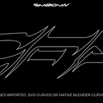
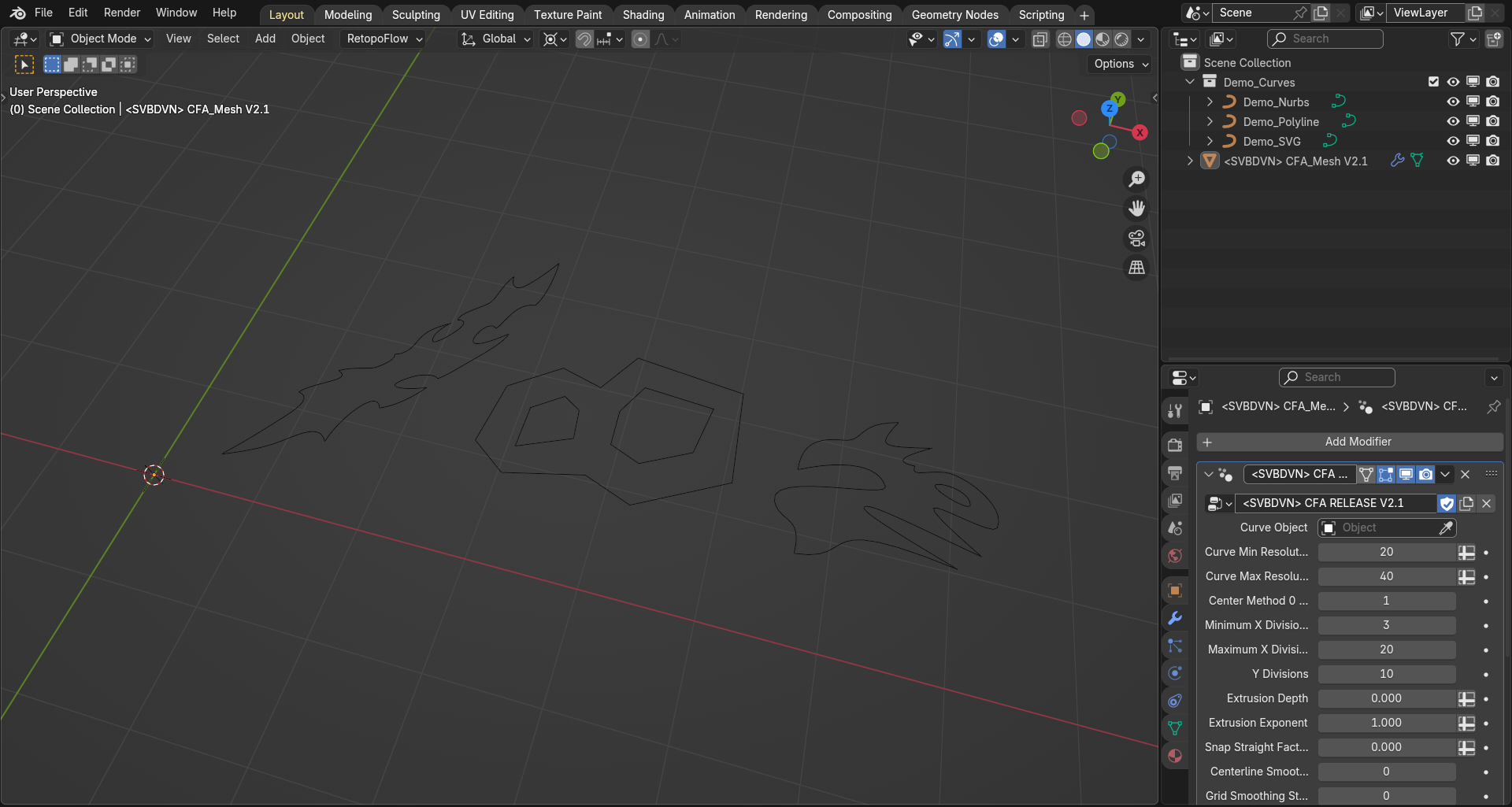
Once opened you should be greeted with the scene layout seen in the above screenshot. The Blender scene contains (3) curve objects called "Demo_Nurbs", "Demo_Polyline" and "Demo_SVG" respectively. It also contains (1) mesh object called " CFA_Mesh" which should have the CFA modifier applied to it. You can append the whole "CFA_Mesh" to your scene or the Geometry Nodes node group which is called " CFA RELEASE V2.1" or whatever the most recent version number may be in place of "V2.1".
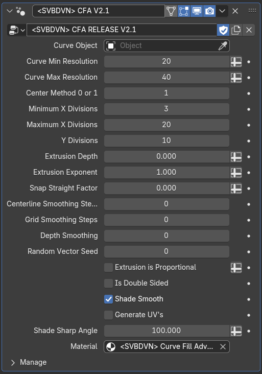
MODIFIER PARAMETERS
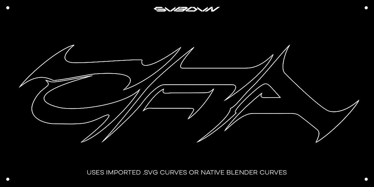
Curve Object: Use this selection box to reference your source curve object in your Blender scene. The splines in the curve object must be set to cyclic or you might get some strange behavior.
Curve Min/Max Resolution: The modifier will resample the input splines to try and ensure even sampling and point distribution. This parameter sets an upper and lower bound of curve resampling resolution. This is based on the lengths of all of the splines in your curve object regardless of spline type.
Center Method 0 or 1: Version 2 of the modifier includes a new center-line calculation method. The new method can, in certain situations, more faithfully represent the macro curvature of a closed spline while preserving the input details. Setting this parameter to 0 uses the old method and setting it to 1 uses the new one. The rest of the modifier functionality should work the same regardless of which method the user has selected. It is up to the user to determine which method best suites their aesthetic goals. If you encounter any topology issues when using the new method, try increasing the centerline smoothing iterations which ought to correct for any such issues.
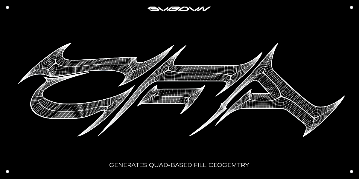
Minimum / Maximum X Divisions: The modifier creates internal geometry by utilizing Blenders native "Grid" primitive. For each grid that it generates it measures the grids length against the other grids, normalizes this value and the maps it to the range set by the minimum and maximum x divisions. This is done to give the ability to increase x density somewhat uniformly across the whole surface mesh. You can tweak these settings to achieve your aesthetic goals.
Y Divisions: This slider controls the y-direction vertex density which, in contrast to the x direction density, is a global value applies to all created grids.
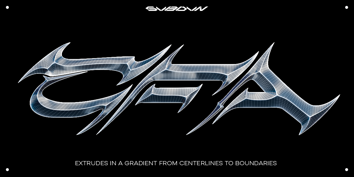
Extrusion Depth: Sets a global Z value that determines the height of the sharp extrusions normal to the plane the curve lies in. The mesh vertices will be shifted normal to the plane in a gradient ranging from the full Z value at the centerlines to no height at the boundaries.
Extrusion Exponent: This parameter sets a value between 0.001 and 2. The modifier raises the normalized Y value of each vertex to this number which has the effect of creating a convex extrusion profile (value 0.001 to 0.999), a linear extrusion profile (value of 1) or a concave extrusion (values of 1.001 to 2). Play around with this slider to achieve different profile shapes.
Snap Straight Factor: This parameter sets a value between 0.000 and 1.000. Increasing this to 1 causes all of the center-lines to snap to straight line segments from their existing end points. This will adjust the attached grids accordingly. This slider can be useful particularly when working with polyline curves where the user may want very linear shapes.
Centerline Smoothing Steps: This slider smooths out only those vertices in the mesh that lie on the center-line curves the modifier uses internally. The smoothing only takes place in the XY plane so the Z values for the vertex positions should not change. Smoothing these positions out can give a variety of different aesthetic effects.
Random Vector Seed: Calculates a per-quad-strip random vector to be used as a random offset value in the texturing phase. See the included material description below for more info.
Grid Smoothing Steps: Similar to the centerline smoothing parameter except that this slider smooths out vertex positions for every vertex in the mesh not just those on the centerlines. The smoothing is constrained to the XY plane so the Z coordinates of the vertices will remain unchanged. The smoothing has a gradient influence where the most smoothing happens to the center vertices and decreases in strength heading towards the boundary vertices which remain fixed and do not move. This allows for positional smoothing while not changing the boundaries of the mesh.
Extrusion is Proportional + Depth Smoothing: Proportional extrusion is an EXPERIMENTAL feature. When the box is checked, the mesh vertices will shift vertically based on the extrusion depth parameter but will now be effected by the relative width of the boundary curves nearest to each vertex location. This feature can create some "lumpiness" in the vertical shift so the depth smoothing slider is included to try and smooth some of this out. Proportional extrusion can create some interesting aesthetic effects but is still under development and may behave in a slightly unpredictable way.
Is Double Sided: Checking this box mirrors the surface across the curve objects XY plane, flips the mirrored geometries faces, and joins the two halves together forming a mirrored, solid mesh. The mirrored side should retain the attributes and UV-coordinates of the original side.
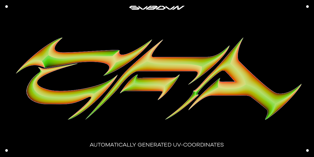
Generate UV's: Checking this box activates the modifiers UV coordinate generation functionality. This can be computationally expensive and can slow down the modifiers calculation time. This checkbox allows the user to switch off the UV generation during the modelling stage and then switch it back on during the texturing phase when the UV's are necessary.
Material: This selection box is used to assign a material to the CFA mesh object. By default the material is set to a simple included material named "Curve Fill Advanced Mat_1". Please refer to the texturing section below for further information on this stock material.
Shade Smooth: Checking this box will set the mesh edges to shade smooth except those edges lying right on the centerlines. These will remain shaded sharp giving the mesh its desired "sharp extruded" look.
Shade Sharp Angle: This slider adjusts the angle below which a mesh edge will be set to sharp shaded. This only effects edges not on the center-lines and not on the outter edge which should always be set to shade sharp.
MATERIAL + TEXTURE COORDINATES
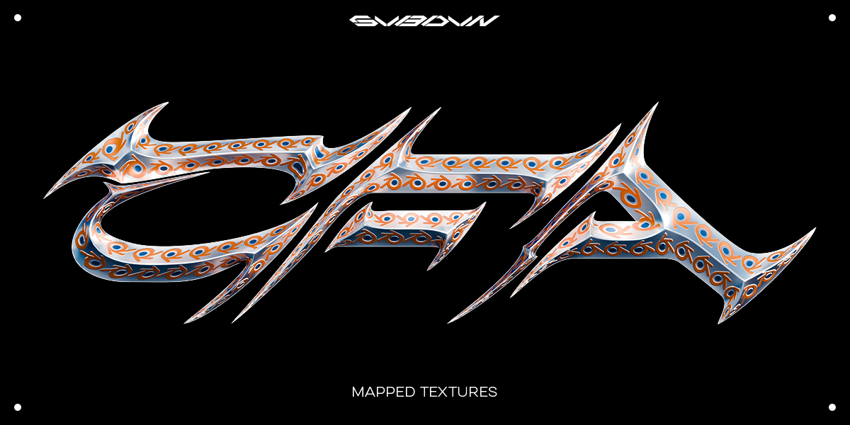
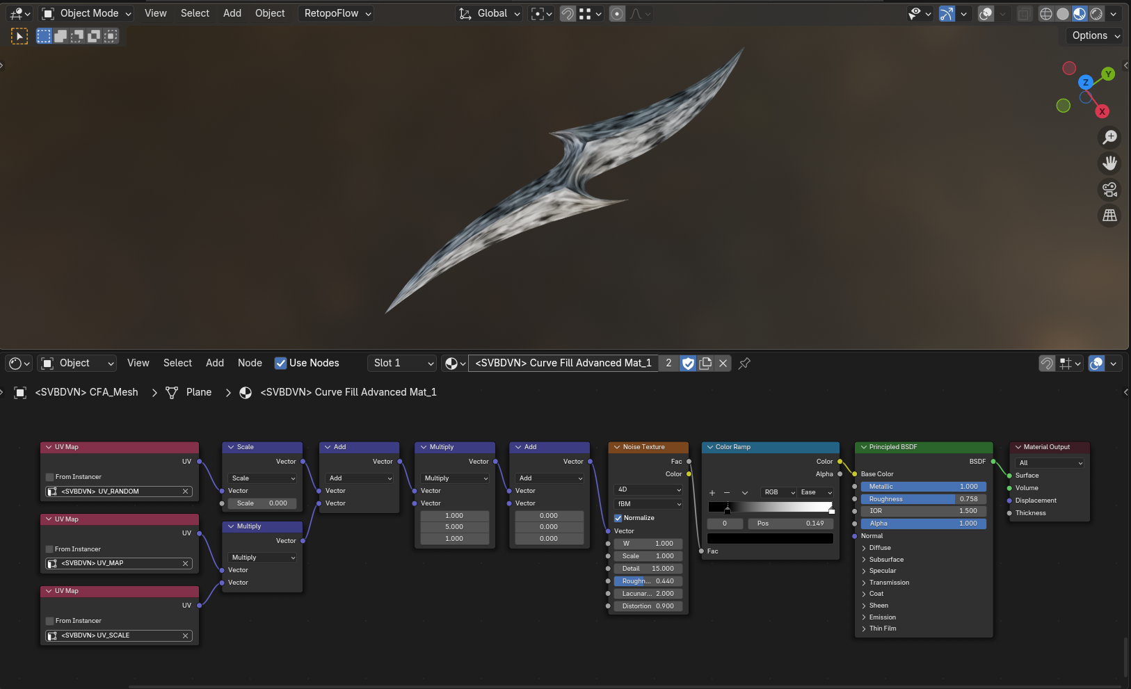
Included in the .blend file is a material named "Curve Fill Advanced Mat_1" that should be selected in the material selection box in the CFA modifier. This is a simple example material included to illustrate the built in UV-coordinate generation that takes place by default inside the modifier.
The modifier creates (3) sets of UV coordinates. Here they are listed along with a brief description of their functionality:
UV-MAP: This is the base set of texture coordinates. These UV's travel along the boundary curve edges mapped to the XY coordinates of the joined grid primitives that make up the surface mesh. The U direction travels roughly tangent to the boundary curves while the V direction travels perpendicular to the tangent at the boundary curve. Using this base set of coordinates you can experiment with mapping either procedural or image based textures to the geometry in a way that "flows" along the edges of the mesh.
UV-SCALE: This is a texture coordinate that contains a single value in the U coordinate particular to all the vertices in each UV-strip. Multiplying the UV-SCALE by the UV-MAP, as seen in the above screenshot, will scale the U coordinates of each mesh strip to try and create a more visually uniform distribution of the mapped texture.
UV-RANDOM: This generates a random XY vector for each UV-strip. The seed value is set in the "Random Vector Seed" parameter in the modifier. Add this vector to the texture coordinates to create a unique texture shift for each UV-strip. This will, for example, allow you to create a random, different noise pattern for each UV-strip. Scale this value before adding it to control the amount of shift.
-
$25
Use this if you plan on using this for your own, personal work. Not for commercial projects.
-
$40
Select this if you plan on using this for commercial projects.
Have questions about this product?
Login to message
| Sales | 50+ |
| Dev Fund Contributor | |
| Published | about 2 months ago |
| Software Version | 4.3 |
| License | Royalty Free |
Discover more products like this
curve extrude Fill Curve fill Curve Fill Blender geometry nodes Advanced topology geometrynodes geometry-nodes-modifier