 Andrea Ciani
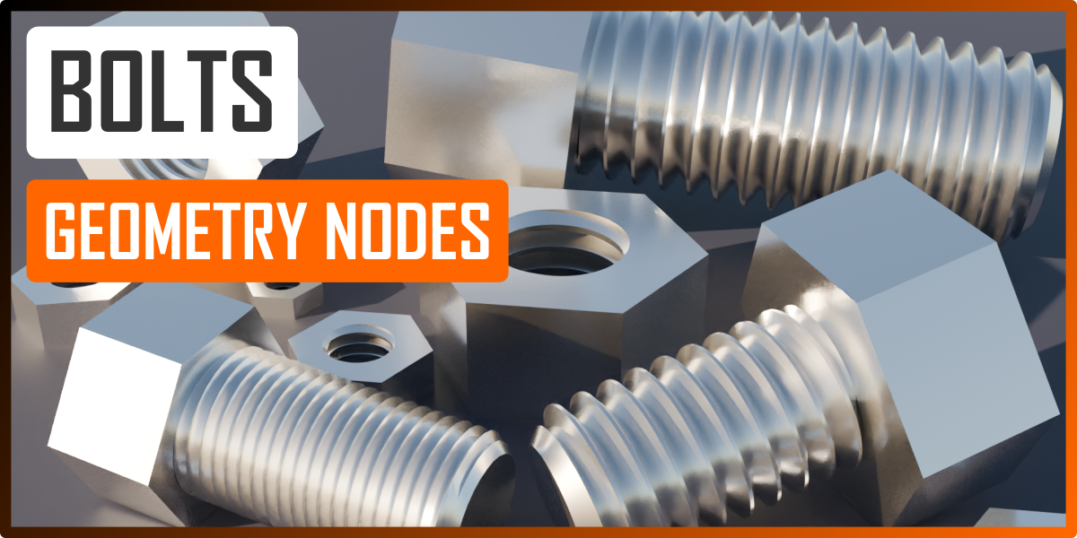

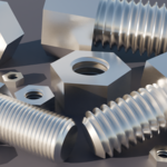
Complete procedural bolts asset for your projects using the standard ISO Metric Thread Table and Metric Coarse Thread Series from M2 to M100.
Made with geometry nodes in Blender v. 4.1.1.
The file also contains the reference images to understand the logic inside the workflow of the geometry nodes setup.
Features
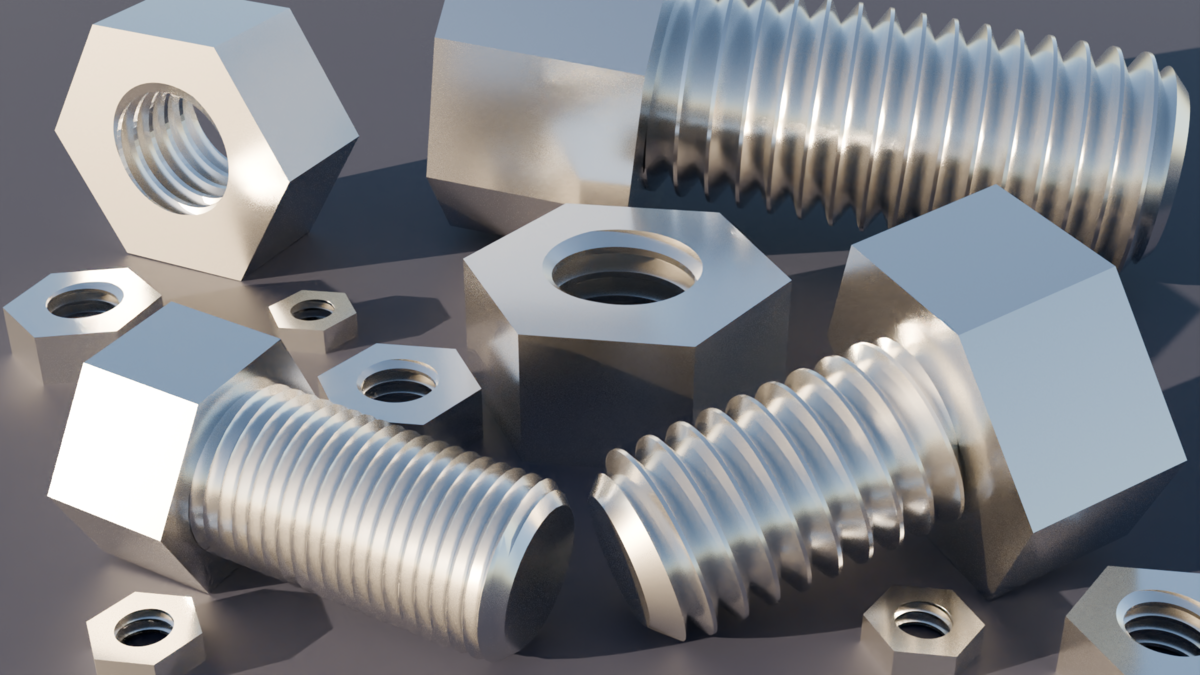
With this modifier you can make several type of screws and nuts only changing the next parameters.
If you have any doubt about strange artifacts on the final mesh please, write to me on this platform, comment on my youtube channel or join on my discord server (link in all my video tutorials description). Most of the time you could increase or decrease some detailed nodes of the workflow that are not exposed outside the modifier.
You'll be able to manage these parameters in the Geometry nodes:
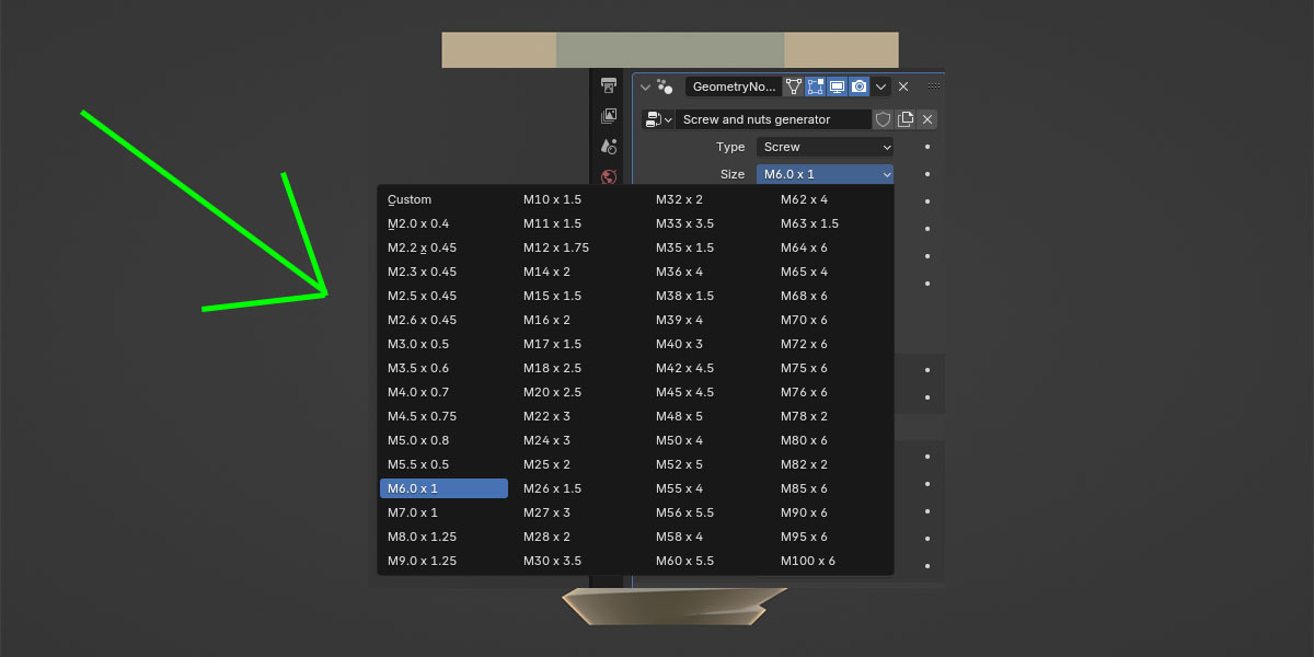
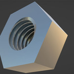
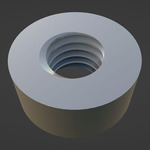
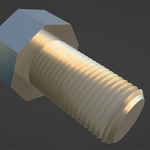
- Type: Screw or Nut
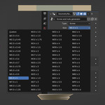
- Size: With this parameter you can choose from the list of all the ISO Metric Thread standard sizes from M2 and M100 or choose the Custom to set custom values for the pitch, the internal and external cut diameters
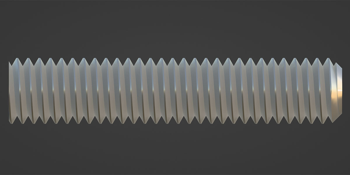
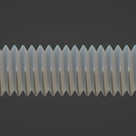
- Height: The height of the thread
- Flip direction: If disabled the thread can be screwed with the right hand (clockwise rotation), if enabled with the left hand.
- Inner diameter (6 sides): This parameter forces the system to calculate the right circumference to assign to the head of the screw or to the nut to have the set value between two parallel faces. In this way you can take the final printed product with steel key or pliers properly. It is recommended to enable this check only for 6 faces. More info in the video tutorial.
- Material: It defines the material to assign to the object.
-
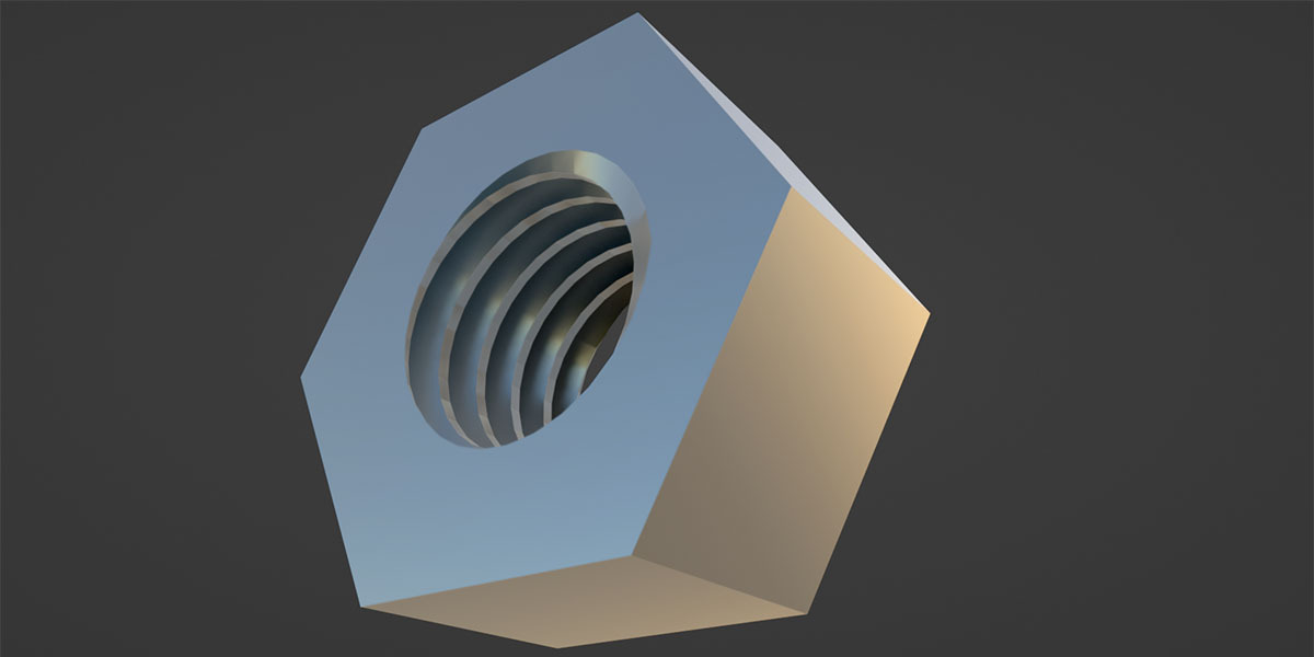
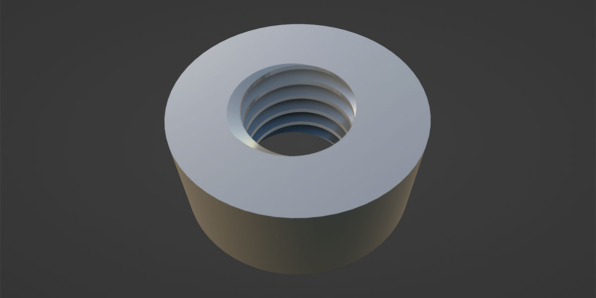
Nut (note: the internal cut to have less grip with screws is always enabled)
- Sides: The number of the external faces of the nut (the resolution)
- Diameter: It defines the external diameter of the nut (not the diameters of the thread inside). Warning, this value needs to be set manually, it is not automatically calculated from the sizes of the thread.
-
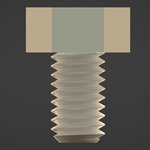
Screw
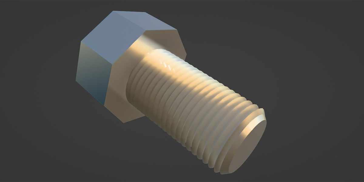
- Cuts & chamfer: Since the boolean operation executed on the geometry can be expensive you can enable this parameter at the end of the setup. It makes the external cutting and the chamfer on the tip of the screw to have less grip between real screws and nuts.
- Head: With this parameter you can choose to have the head on the screw or maintain only the thread alone.
- Head Sides: The number of the external faces of the screw head (the resolution)
- Head Diam.: It defines the external diameter of the screw head (not the diameters of the thread). Warning, this value needs to be set manually, it is not automatically calculated from the sizes of the thread.
- Head Height: The height of the screw head
-
Custom sizes
- Pitch: This defines the distance between two crests of the thread.
- Cut min diam. thread: It defines the minimum diameter already cut for the NUT (not for the screw). From this parameter the system will calculate all the others to get the correct profile tolerances. I remember that for reference, the center of the circle defined by this diameter is on the axis passing through an hypothetical screw (see the reference images).
- Cut max diam. thread: It defines the maximum diameter already cut for the SCREW (not for the nut). From this parameter the system will calculate all the others to get the correct profile tolerances. I remember that for reference, the center of the circle defined by this diameter is on the axis passing through the screw itself (see the reference images).
-
Animation
-
Offset: It allows you to automatically offset and rotate the piece to maintain the right proportion between offset and rotation.
This parameter is always related to the axis passing through the screw or the nut. In this way you can rotate the screw or nut in the object mode and play with this parameter without worries.
-
Offset: It allows you to automatically offset and rotate the piece to maintain the right proportion between offset and rotation.
Fell free to use it adding keyframes and tweaking the curves animation with the graph editor.
Warning! Before printing this pieces with a 3d printer it is highly recommended to print few pieces of the final products for tests, putting them in the right application before massive printing. This is recommended to avoid throwing away unusable material.
You can find useful information about it on the Export to 3d printer section of the video tutorial.
Uses
This product contains the file used in the video tutorial but cleaned and structured to be used as a file asset.
To use this generator in your project you can just use the downloaded file as is or open your project, use the Append menù of Blender, selecting this file, then NodeTree and then Screws and Nuts generator. After the append you will be able to add this geometry nodes modifier on any meshed to make the desired bolt.
An alternative is save the example file in the paths of your asset browser set in your preferences and use the Screw example object as an asset (its name will be Screw).
Tutorial
If you want to learn how i made it check the video below, have fun and if you like what i'm doing please subscribe on my YT channel checking the bell icon to be notified on the new posted videos! :-)