 Lazy3D
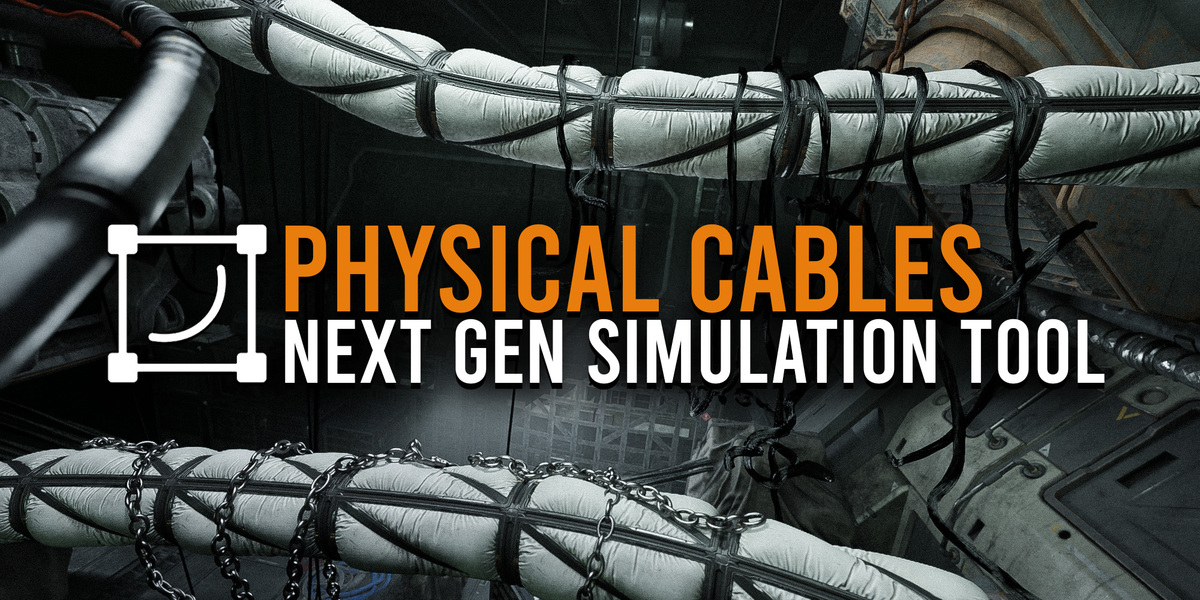


Better use PDF file in Download Section
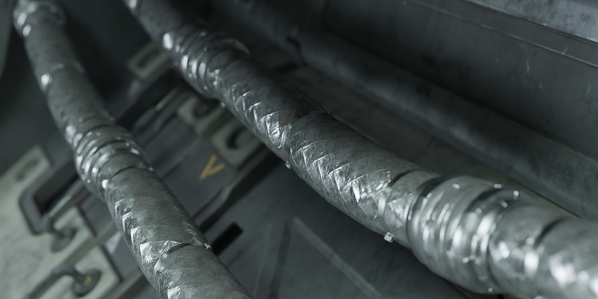
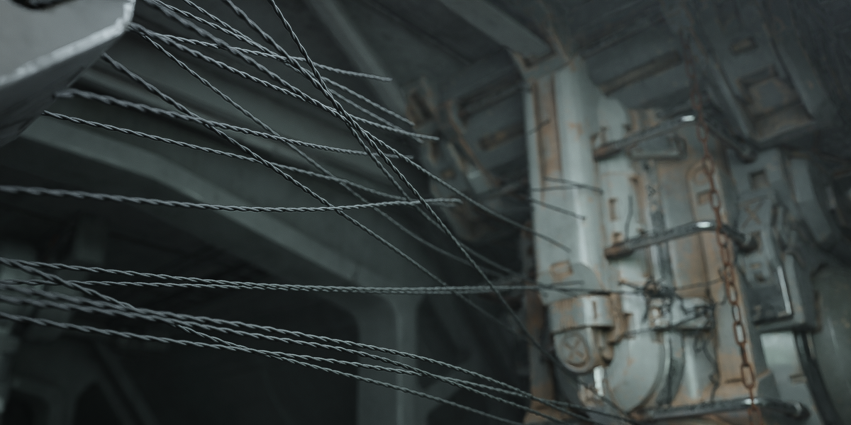
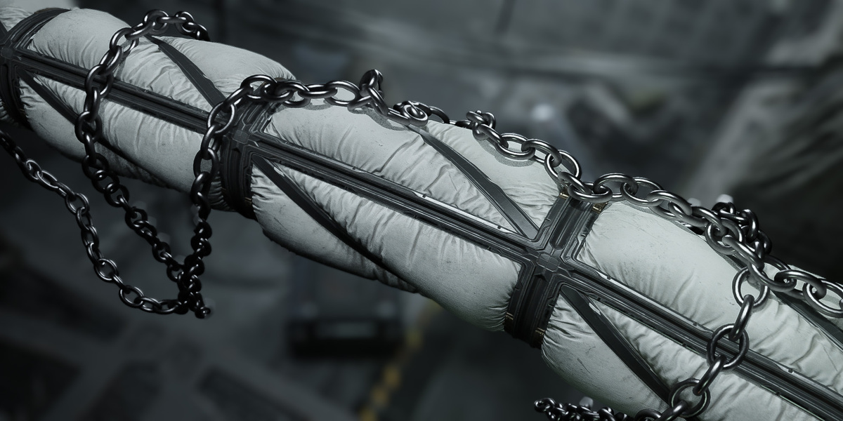
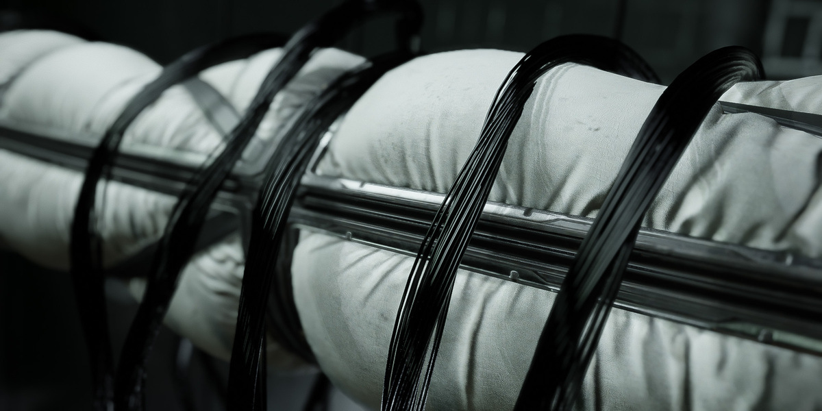
Physical Cables Asset Pack Content


Physical Cables Addon
Documentation
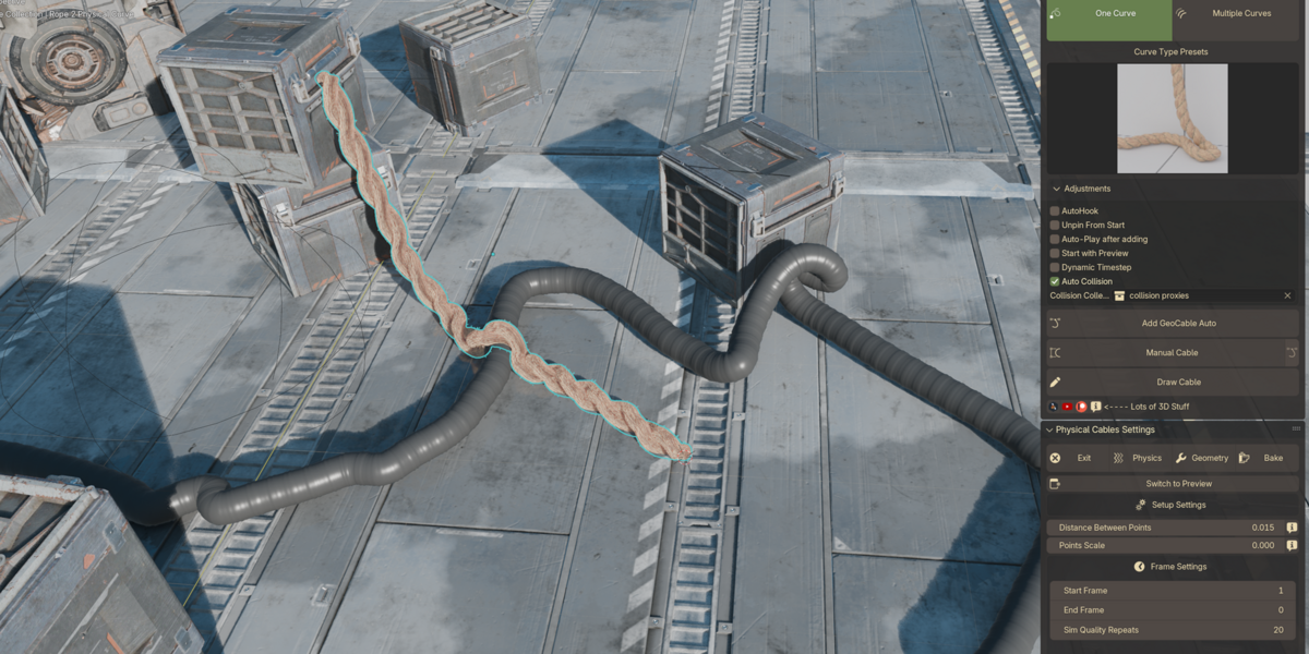
UI Overview
1. Mode Selection:
One Curve: Creates a single cable. This is useful for cases where only one cable is needed for a specific connection or effect.
Multiple Curves: Allows the creation of multiple cables at once, which is helpful when generating cables in bundles or more complex wiring setups.
2. Curve Type Presets:
A list of predefined cable curve styles to choose from.
3. Adjustments:
AutoHook: Automatically adds hooks to both ends of the cable for easy control.
Unpin From Start: Removes the fixed pin constraint from the start of the cable during simulation.
Auto-Play after adding: Automatically runs simulation once the cable is added to the scene.
Start with Preview: Enables a preview mode right after importing a curve.
Dynamic Timestep: Adjusts the physics timestep to allow more accurate simulation results, especially useful for longer or more complex cables.
Auto Collision: Ensures the cable will collide with other objects in the scene during simulation, preventing it from passing through geometry.
4. Action Buttons:
Add GeoCable Auto:
When you press the Add GeoCable Auto button, a pop-up menu appears, allowing you to further configure the cable's position and setup. This menu provides options to set the starting and ending points of the cable.
5. Physical Cables Settings:
Similar to the previous UI version, the settings are divided into tabs for easy access:
Setup: Basic configuration for generating cables.
Physics: Parameters for physics-based simulations, such as gravity or elasticity.
Geometry: Customization of the cable’s geometric properties.
Bake: Bake the simulation for performance improvements and final adjustments.
Workflow: One Cable
· Set the Start and End Points:
- Positioning the 3D cursor: Before starting, place the 3D cursor where you want to position the points. The cable's start and end points will be set at the location of the 3D cursor.
· Setting the Start Point:
- Once the 3D cursor is in the correct position, click the "Set Start Point" button.
- An empty object will be created at the 3D cursor’s position, which will act as the start point of the curve.
· Setting the End Point:
- Similarly, place the 3D cursor where the end point should be, and click the "Set End Point" button.
- Another empty object will appear at the cursor’s position, marking the end of the curve.
· Important Note:
- Do not delete the empty objects before finalizing the curve, as this could lead to errors in the cable creation process.
· Moving the Empties:
- After creating the empty objects, you can move them anywhere in the scene to fine-tune the cable’s positioning.
· Creating the Curve:
- Once you’re satisfied with the positions of the start and end points, click the "Create Curve" button.
- The add-on will generate a cable connecting the two points.
- After the cable is created, the empty objects will be automatically removed.
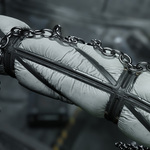
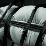
Workflow: Cables Between 2 Objects
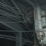
To create cables between two objects, the process is quite straightforward. First, select the first object, then click the "Set 1st Object" button. Afterward, select the second object and press "Set 2nd Object." Once both objects are selected, click on "Connect 2 Objects." After a short moment, cables will appear between the two objects, automatically connecting them as shown in the screenshots.
Adjusting Curve Settings:
In the Setup Settings tab, you will find key parameters to adjust the properties of the created curves, as highlighted by the arrow:
- Density:
- Controls the number of curves generated between the two objects.
- Distance Min:
- Defines the minimum allowed distance between the curves.
- Seed:
- This setting introduces randomness to the curve layout. Changing the seed value will shift the random positions of the curves.
- Align Curve Handle:
- Adjusts the smoothness or bend of the curves. If set to 0, the curves will be straight; increasing this value will introduce curvature.
Enabling Vertex Groups for Control Over Curve Distribution:
-
First Object Vertex Group and Second Object Vertex
Group:
To control exactly where the curves will connect on the objects, you can enable vertex groups: - Select the first object and enter Edit Mode.
- Create a new Vertex Group (as shown in the screenshot).
- Select the faces or vertices where you want the cables to appear, then click Assign (refer to the screenshot for detailed steps).
- Repeat this process for the second object.
After setting up the vertex groups, assign the names of these groups in the First Object Vertex Group and Second Object Vertex Group fields.
Workflow: Cables Between Objects In Collection
To create automatic cables between all objects in a collection, follow the steps outlined in the screenshots:
- Determine the Objects for Cables: Select the objects that you want to connect with cables.
- Group Objects in a Collection: Add the selected objects into a single collection. This collection will serve as the target collection for cable distribution.
- Set the Target Collection in the UI: In the interface, add the collection as the "Target Collection" for cable distribution.
- Place the 3D Cursor: Set the 3D cursor to the desired position. This position is crucial because it determines where the distribution controller for the cables will be placed in the scene. If you don't set the 3D cursor, the controller will appear at its previous location, which might make it difficult to find in the scene.
- Check the Controller and Curve: After generating the cables, ensure that both the controller and the curve are placed outside of the target collection. If they are added to the collection by mistake, the effect will not work. If this happens, simply move them to a different collection.
If you do not see any effect, try increasing the Density or adjusting the empty (controller) that manages the distribution effect. It may help to move the target objects slightly closer to each other.
Now let's move on to the Distribution Settings, located in the Setup panel. Below is a description of each setting:
- Density: Defines how dense the cables will be distributed between the objects.
- Distance Min: Sets the minimum allowable distance between the cables.
- Distance to Objects: Determines how far from the objects the cables will start being generated. A higher value will make the cables shorter, while a lower value will position the cable ends closer to the target objects.
- Length Max: Specifies the maximum allowed length for the cables between objects.
- Length Min: Defines the minimum cable length that will be generated.
Workflow: Curve Setup
Key Steps:
- Switch to Preview Mode:
- The first button in the setup panel switches to preview mode. This mode simplifies the display of the curve, showing only the points. It’s crucial to use this for better visualization when adjusting the curve.
- Adjust Distance Between Points:
- This socket controls the spacing between points along the curve. If the distance is too large, the curve may break apart under tension. Ideally, points should be close enough to create a smooth, continuous curve. The example in the first screenshot shows an ideal configuration with points close enough to avoid gaps.
- Points Scale:
- This socket controls the size of the points. It impacts both the radius of the generated geometry and how they interact with physics simulations.
- Handling Large Distances Between Points:
- The second screenshot shows a setup with points spaced too far apart, causing gaps or disconnections. If you find that increasing the distance between points results in curves breaking apart but you want to maintain the longer distances, you can fix this by adjusting the Physics tab (go to 5 step).
- Bending in Physics:
- Set the bending stiffness (or similar parameters) to zero or a very low value. This ensures that the curves don’t snap under tension and can bend or adjust smoothly based on collisions with other objects, preserving the overall shape.
By balancing the distance between points and the physics settings, you can create smooth curves without breakage, even under more demanding conditions.
Ideal Position 1
Ideal Position 2
Bad Distance 1
Frame Settings Overview:
- Start Frame & End Frame:
- If the End Frame is set to 0, the simulation will run indefinitely until your timeline ends. This is useful for longer, continuous simulations that do not need to stop at a specific frame.
- Sim Quality Repeats:
- By default, the simulation quality repeats are set to 20. It is recommended to leave this value unchanged for most use cases.
- Lower values make the simulation more elastic and "bouncy," while higher values result in a stiffer, more rigid simulation. A value of 20 strikes a good balance between flexibility and stiffness.
Time Step Settings:
- Delta Time / Time Step:
- If enabled, it activates a time step that controls the pace of the simulation.
- When Dynamic TimeStep is enabled, the time step will be calculated based on the length of your curve. Keep in mind that it computes this for each spline individually.
- Adjusting the Timestep value will slow down or speed up the simulation. A lower value will slow the effect considerably, allowing for a more controlled, smoother result. Experiment with this setting to achieve the desired effect.
- Recommendation:
- For longer curves, it’s highly recommended to use Dynamic TimeStep to maintain proper synchronization and control over the simulation.
Collision Settings:
- Enable Collision:
- By enabling this option, collisions with other objects will be accounted for in the simulation. Below, you can assign a specific collection to act as the collision group. Only objects in this assigned collection will be treated as colliders during the simulation.
Feel free to experiment with these parameters to fine-tune your curve simulations and collision effects
Workflow: Physics Setup
· Collision Settings:
- Enable Collision: Enable this to activate collision physics. You can select a specific collection of objects as the "Colliders" collection.
- Check Inside: If this option is active, the curve will check for collisions not only on the surface of the objects but also from within the meshes.
- Bounce: Controls how much the curve will bounce when it interacts with surfaces. A higher value will cause stronger bounces.
- Friction: Determines how much the curve will slow down upon interacting with a surface. A higher friction value will reduce sliding.
· Pin Settings:
- Start & End: These options control whether the start and end of the curve are pinned in place. By default, both are pinned.
- Start Width / End Width: These parameters adjust how many points at the start or end of the curve are affected by the pinning.
- Factor: Controls the overall influence strength of the pinning points. A lower factor means weaker pinning, allowing more flexibility in the curve.
· Stiffness Settings:
- Tension: Defines how much the curve resists stretching. Lower tension allows more stretch, while higher tension keeps the curve tighter.
TENSION = 0.1 TENSION = 1
For Tension, avoid setting it to zero, as in certain situations, your curve may break apart. For a stable simulation, a recommended minimum tension value is 0.1, which will keep the curve taut without making it too stiff.
- Bending: If the bending value is set to zero, the curve will be tightly stretched, resisting any sagging. At a value of one, the curve will sag more under its own weight. For a stable curve where points do not move much, set the value between zero and one but not exactly one, such as 0.7 or 0.8. This will make the curve more stable because at the value of one, the curve will constantly try to droop downwards. Therefore, for more predictable and controlled results, use values slightly below one.
BENDING = 0
BENDING = 1
- Hardness: This parameter influences how rigid the curve behaves. Higher values result in a stiffer curve simulation.
· Dynamics:
- Damp Factor: Controls how fast the curve loses momentum and comes to rest. A higher damp factor will slow down the curve quicker.
- Force Factor: Defines how much external forces (like gravity or wind) affect the curve’s movement.
· Wind Settings:
- Wind Force: Adjust the wind's force acting on the curve. The default value is set to (-1) for gravity. Adjust the X, Y, and Z components to control wind direction and intensity.
- Advanced Wind Settings: When activated, advanced wind controls replace the simple directional wind with more complex wind simulations, including turbulence, noise scale, and other properties.
- Wind Scale: Adjust the granularity of the wind turbulence. A smaller value increases the fine details of the wind effect, while a larger value smooths it out.
· Break Settings:
- Enable Break: This allows curves to break if they reach a certain distance threshold.
- Distance Threshold: Sets the minimum distance between points on the curve before the system considers the curve "broken" and applies breaking physics.
- Probability: Controls the likelihood of a break occurring. A value of 1.0 guarantees a break when conditions are met.
· Chop Settings:
- Enable: Allows the selection of an object that can "cut" or interact with the curve in a special way.
- Distance Threshold: Sets the sensitivity to how close the cutting object needs to be to cause an effect on the curve.
· Self Collision Settings:
- Enable: Activates self-collision detection for the curve, ensuring that different parts of the same curve don't pass through one another.
- More Stable: Makes self-collisions more robust and stable but can slow down the simulation slightly.
Misc Settings Panel:
- Enable More Pinners:
- Once activated, this option opens a menu that allows you to assign between one and four pinners (anchoring points) to your curve.
- For better usability, I recommend enabling the "Visualize Pinner Points" option. This will help you visualize and locate the exact positions of the anchor points on your curve for better orientation.
Pinner Points Visualized 1
- Adjusting Pinner Points:
- You can adjust the position of each pinner using the Point Index value. This will determine which part of the curve gets anchored.
- After determining the position of the anchor point you want to set, create or select an object in your scene (for example, an Empty object). Move this object to the exact coordinates of the anchor point.
- Next, in the Object socket of the pinner settings, assign the object you’ve just placed (e.g., the Empty object).
- Finally, enable the switch to activate the anchoring for each pinner. Follow this process in order: determine the point location first, add the object to the scene, and only then enable the anchoring.
3.
- Enable All Curves:
- This option applies if you are working with multiple splines within your curve. When activated, it allows you to manage anchor points and settings across all the splines within a single curve structure.
Hang Settings:
- Enable Hang:
- This section is designed for hanging objects on the curve.
- Simply enable the option, select the object you want to hang from the curve, and adjust its position along the curve using the Hang Object Position setting.
- You can further modify the object's position, scale, and rotation offsets to control how and where the object is hung relative to the curve.
- Don’t forget to assign a material to the hanging object for it to render correctly in the scene.
Workflow: Geometry Setup
The geometry settings are highly customizable depending on the specific type of cable you're working with. Each cable type has its own unique set of parameters that you can adjust to fit your project's needs.
As the options in this panel vary greatly between different cable types, I won't go into detail for each one here to avoid overcomplicating the documentation.
Workflow: Bake Settings
Baking Panel
In this panel, you will find two modes for baking: Still Mode and Animation Mode.
- Still Mode: If this mode is selected, the bake will capture the physical curve at the current frame.
- Animation Mode: If this mode is selected, the bake will capture the curve’s animation over the specified range of frames in your timeline.
Key Buttons:
- Bake: This button will bake all physical curves in your scene according to the selected mode. If you're in Animation Mode, it is recommended to save your project before baking, as it will bake the curve across the entire range of frames specified in the timeline. For example, if your timeline starts at frame 20 and ends at frame 250, only this segment will be baked.
- Trash Icon (Next to Bake): Pressing this button will delete any existing baked data.
- Bake As Static Mesh: This button converts your physical curve into a static mesh. The mesh will retain its geometry but lose its physics-based simulation.
Most Common Questions and Problems
1. My curve is breaking
apart, what should I do?
Solution:
Ensure that the distance between points in the Setup
section isn't too large or too small. You can adjust this under the distance
settings to make sure the curve stays connected.
If the curve collapses or breaks apart during fast movements, try reducing the Timestep in the physics
settings for a smoother simulation.
Alternatively, you can set the Bending value
in the Physics Settings to 0 or a small value, such as
0.1 or 0.2, to prevent the curve
from sagging or breaking under stress.
2. How do I make the curve more taut?
Solution 1:
- In the Physics settings, set Bending to 0. This will make the curve tighter and more resistant to sagging.
Solution 2:
- Slightly increase the distance between points in the Setup section. This will help the curve become more taut and properly stretched.
3. My cable's points are jittering when sagging. How can I fix this?
Solution:
- The issue may be caused by too many points in your cable and a high Time Step.
- To avoid point oscillation, lower the Bending value in the Physics settings to 0.7 or 0.8, but avoid setting it to 1.
- Reducing this value allows the points to relax a bit, especially in the most tense areas of the curve, preventing the jittering effect.
4. My cable is too wavy, how can I make it stiffer?
Solution:
- Set the hardness value to 1.
5. The cable is oscillating too much, how can I fix that?
Solution:
- Set the bending value to 1. If you need more stiffness, you can either increase the distance between points or set hardness to 1. This issue usually occurs when pin points are off and bending is set below 1, causing the points to constantly search for a reference force in the next frame.
-
$17
15 Geometry Presets, All Functionality.
-
$25
32 Geometry Presets, All Functionality + Physical Cables Asset Pack (over 100 assets for your asset browser - content info in the top of documentation tab).
Have questions about this product?
Login to message
Discover more products like this
Generator addon modifier winter24 cables cables cables cables wires sci fi Geometry creating cabls cablerator bfcm24 pipes loveblender free Cable tubes geometry nodes spring24 geometrynodes creating cables create cables summer24